A useful observation programme begins with a decision that somebody can act on. Before selecting imagery or instruments, define the area of interest, the people responsible for inspecting it, and the time available for a response. This planning perspective connects remote measurements with the practical questions that shape a survey or monitoring service. The aim is to identify which observations would change a decision, how supporting evidence would be collected, and what should happen when information is incomplete. A clear plan makes later technical choices easier to assess against an operational purpose.
This working guide considers building a spacecraft power and energy budget along changing sandy shorelines. The immediate decision is to review shoreline positions over time. Useful reference evidence includes acquisition context, field positions and consistent shoreline definitions. The case is an illustrative planning context, with assumptions to check against the actual sensor, landscape and project requirements.
Distinguish power from stored energy
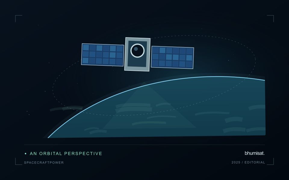
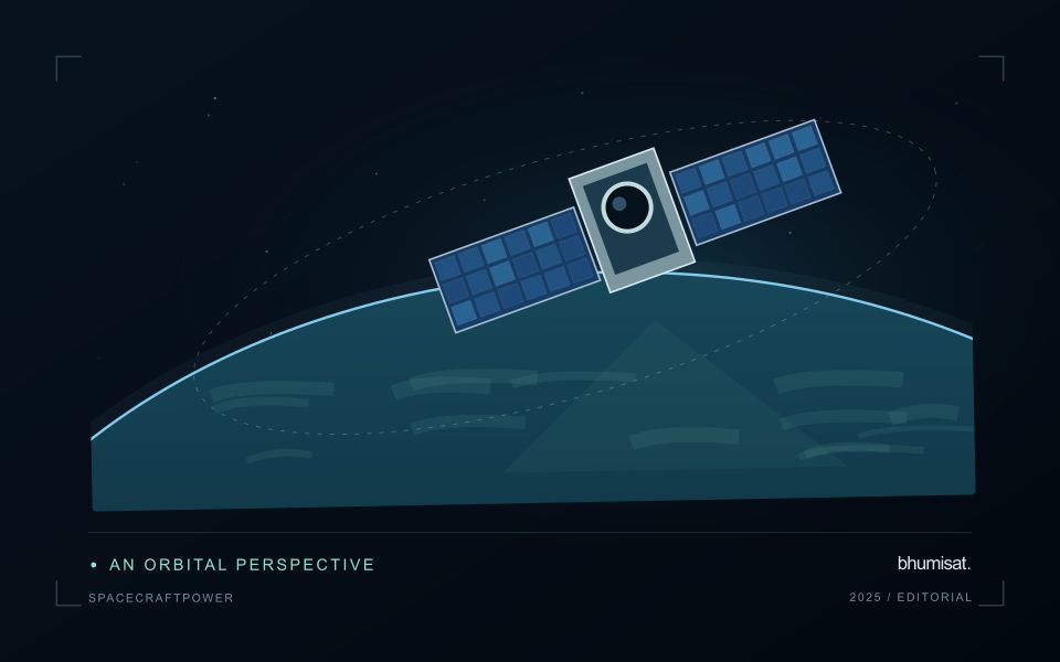
A spacecraft electrical power system must generate energy, store it when necessary and distribute it reliably to the loads. Power describes the rate of energy use, while energy describes consumption over an interval. A transmitter may have a high instantaneous demand even if it operates briefly. Conversely, a modest continuous load can dominate the daily energy budget. Both views are needed to size the system.
List operating modes and their duration: standby, imaging, processing, communication, safe mode and any relevant transitions. Include heaters, power conversion losses and supporting electronics rather than counting only the camera and radio. Identify loads that overlap in time and those that can be scheduled separately. Peak current and startup behavior can challenge distribution hardware even when the average energy balance appears comfortable.
Check realistic orbit and lifetime conditions
Solar generation depends on illumination, array orientation, temperature and the condition of the cells and associated hardware. Eclipse intervals require stored energy, and imaging or communication pointing may reduce favorable Sun exposure. Evaluate the time sequence across representative orbits rather than comparing one average generation number with one average load. Consider the expected decline in performance over the mission and apply clearly justified design margins.
Battery sizing must consider usable capacity under the planned temperature, discharge rate and cycling conditions. Nominal capacity alone does not describe what is safely available in service. Charging limits, allowed depth of discharge, ageing and monitoring requirements influence the operating envelope. Thermal design and power planning therefore need to evolve together. A heater can protect a battery while consuming the energy that the battery is expected to deliver.
The distribution system should detect and isolate relevant faults while preserving essential functions. Define which loads are shed when energy becomes scarce and what conditions allow them to return. Safe mode needs its own verified energy balance and a credible path toward recovery. Telemetry should support comparison between predicted and measured generation, consumption and battery behavior. Test the budget with realistic duty cycles, instrument startup sequences and communication sessions, then update the model using measured component performance. A defensible power plan explains the worst cases and the assumptions behind its reserve, allowing observation schedules to be adjusted before they threaten spacecraft survival.
The setting: Changing sandy shorelines
A shoreline is not always one fixed boundary that every observation measures in the same way. The visible water edge, a vegetation boundary and another mapped coastal indicator can represent different features. A monitoring programme should define its chosen shoreline consistently before comparing dates. Tidal conditions, wave state, seasonal beach changes and the geometry of the image can all influence the position recorded, even without a lasting change in the coast.
Spatial resolution and alignment determine the precision with which a boundary can be located. A sharply drawn line on a map should not imply more positional certainty than the observations support. Compare acquisitions under suitable conditions and retain the information needed to examine their differences. Mixed pixels, shadows and narrow coastal features may require manual review or an uncertainty zone rather than an automatic interpretation at every location.
Field validation should use the same shoreline definition as the image analysis and record when and how a position was measured. A visit under different water conditions may represent a different boundary even if its coordinates are accurate. Evaluate change over appropriate distances and periods, and avoid treating every small mapped displacement as erosion or deposition. A transparent product shows the observed positions, their dates and the uncertainty relevant to the decision being considered.
Maintain the geographic units of analysis
Many observation services summarise measurements within a field, management block, catchment, forest unit, or other mapped boundary. The meaning of that summary depends on whether the boundary accurately represents the unit being discussed. Start with a clear source for the geometry and record its date, coordinate reference, and intended use. A boundary drawn for visual orientation may require additional checking before it becomes a measurement unit.
Inspect overlaps, gaps, narrow fragments, and features that may have changed since mapping. A geometrically valid polygon can still describe an outdated operational unit. Ask the responsible team how divisions, mergers, new infrastructure, and management changes are recorded. Where pixels or reference measurements cross a boundary, define how they are assigned or excluded so that results remain comparable between analysts and processing runs.
Version the boundaries alongside the observations. If a unit changes, preserve a relationship between the previous and revised geometry rather than replacing the history without explanation. Comparisons through time should identify whether they use a constant spatial unit or the operational units valid at each date. This makes it easier to distinguish a change in the measured surface from a change introduced by the geography used to summarise it.
Connect observations within a catchment
Water-related observations often depend on processes beyond the immediate pixel or sampling location. Begin by identifying the geographic relationships that are relevant to the question: upstream areas, connected drainage paths, contributing land uses, and the receiving water body. A local pattern may be easier to interpret when placed within that wider setting. The catchment boundary is a useful organising unit, but its suitability should be checked against the process and observation scale.
Combine the remote observation with contextual records that can help explain its timing and spatial pattern. Rainfall, water level, land management, and known interventions can influence what is observed. Preserve the dates and geographic meaning of those records rather than treating them as timeless attributes. Where drainage connections are uncertain or change with conditions, state the limitation and consider whether additional mapping or reference observations would materially improve the interpretation.
Plan reference sampling across locations that distinguish plausible explanations. A set of measurements concentrated at an easily accessible outlet may provide a different view from one that also represents tributaries, source areas, and contrasting conditions. Document how each location contributes to the evaluation. Interpret spatial agreement with care, because connected observations can share influences and may not provide independent evidence. The resulting workflow should connect local measurements with a defensible account of the wider system they help describe.
Bring the evidence back to the decision
The practical outcome should be a short observation plan that another team can follow. It should name the decision, the required evidence, the responsible roles, and the conditions that trigger a field visit or further analysis. Keep the plan small enough to test, then revise it using the results of real inspections. A useful monitoring workflow improves because its assumptions are examined systematically, and its observations remain connected to decisions throughout the process.
Sources & further reading
Explore the bhumisat spacecraft concept and our vision towards 2030, or return to the journal.