A method that produces a plausible result has not automatically demonstrated that it works for its intended users. Validation requires a defined question, suitable reference evidence, and an evaluation design that reflects how the method will be used. This perspective examines which observations should be compared, how they should be sampled, and which errors matter in practice. It also considers the difference between evidence used to develop a method and evidence reserved for evaluating it. The objective is a test that can reveal weaknesses as well as confirm useful performance.
This working guide considers synthetic aperture radar for land monitoring across periurban land transitions. The immediate decision is to review changing land-use boundaries. Useful reference evidence includes dated land-use observations and parcel-level reference records. The case is an illustrative planning context, with assumptions to check against the actual sensor, landscape and project requirements.
The setting: Periurban land transitions
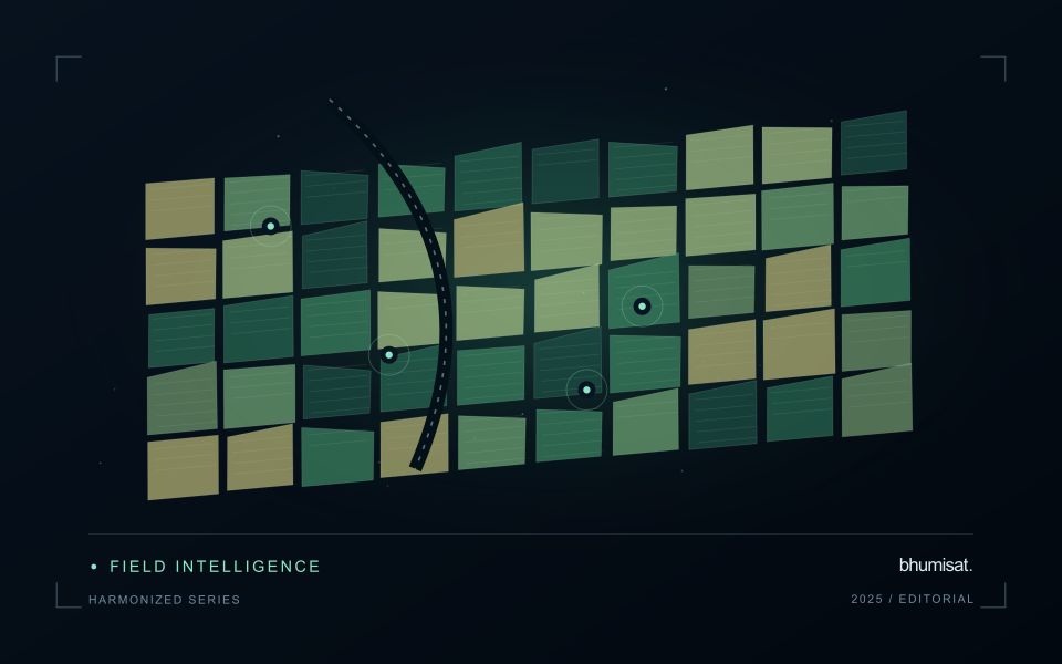
A periurban landscape can contain agricultural fields, new buildings, open construction areas, roads and vegetation in close proximity. Changes may occur in small patches and follow different stages of development. A monitoring system should define whether it is mapping surface cover, documenting a change in land use or prioritising locations for a site review. These tasks are related, but a bare surface in an image does not automatically establish its eventual use.
Maintain parcel or management boundaries where they are relevant and review whether the image resolution can separate the features of interest. Small geometric offsets can alter a comparison along narrow roads or building edges. Seasonal crop changes, temporary clearing and construction activity may produce different explanations for similar spectral patterns. Retain the acquisition dates and quality context, particularly when the available observations leave uncertainty about when a transition occurred.
Field validation should identify the current surface and its documented use as separate attributes. Record the location, date and spatial extent represented by each observation, and include unchanged parcels as well as obvious transitions. A useful product provides an auditable inventory of observed changes and their uncertainty. More specific conclusions about development status, ownership or future use require appropriate external records rather than inference from image appearance alone.
Radar measures a different interaction with the landscape
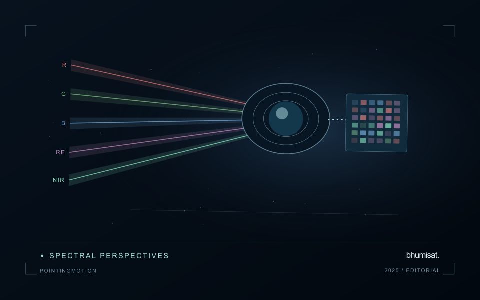
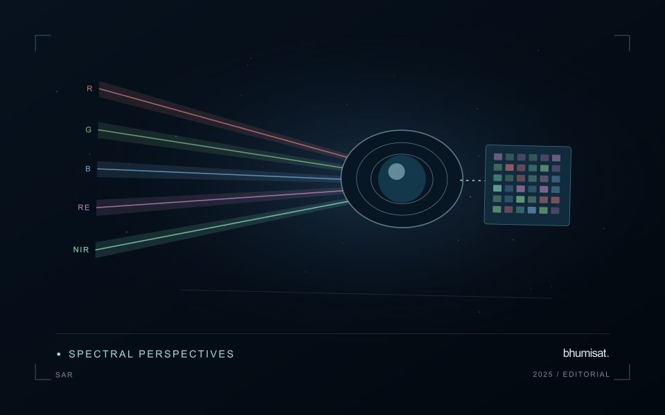
Synthetic aperture radar is an active observing technique: the instrument transmits microwave energy and measures the returned signal. Its image therefore represents a different interaction with the landscape from reflected visible or near-infrared sunlight. Radar can provide observations in conditions that limit optical imagery, but its response still depends on the instrument and scene. Backscatter should not be read as a universal moisture or vegetation score. Surface structure, water, roughness, geometry and the arrangement of scattering elements can contribute to the measured return.
Wavelength and polarisation influence which interactions are emphasised. The same agricultural field can change its radar response after rainfall, tillage, crop development or harvest, and several of those processes may occur together. The viewing direction and incidence angle also matter. A time series assembled without controlling these factors can contain differences that look like an environmental trend. Retain orbit, geometry, polarisation and processing metadata, and choose comparisons that are appropriate for the physical interpretation the application is intended to support.
Compare like with like before drawing conclusions
Radar images commonly contain speckle, a granular appearance associated with coherent measurement. Filtering or aggregation can make patterns easier to interpret, but it also changes spatial detail and statistical behaviour. Select processing around the reporting scale and evaluate its effects near boundaries. Terrain can create additional geometric challenges, including compressed or hidden areas in the radar view. A map should identify where the observation is difficult to interpret rather than filling every location with an equally confident result.
Complementary evidence helps distinguish plausible explanations for a radar change. Combine suitable optical observations, rainfall or management records and field measurements when they address the actual question. Validate a proposed model on independent locations and conditions, including cases where the expected relationship fails. A dark water surface in one setting does not establish a universal flood rule, because rough water, vegetation and built structures can produce different responses. Radar becomes valuable when its particular measurement physics is incorporated into a carefully defined monitoring workflow, with geometry and uncertainty remaining visible to the analyst and user.
Plan the evidence needed for calibration
Calibration connects an instrument's recorded response with a measurement that can be interpreted consistently. Begin by identifying which aspects of the response matter to the application: variation across channels, changes with operating conditions, geometric alignment, or differences between repeated observations. A calibration plan should state the quantities being assessed and the evidence needed to determine whether the response is sufficiently characterised for the intended use.
Design tests around controlled and documented conditions. Record the reference source, instrument configuration, exposure settings, temperature conditions, and processing applied to the measurements. Repeat suitable observations to investigate variability and distinguish a consistent response from a single favourable result. The reference itself has limitations, so preserve its characterisation and avoid assuming that every difference originates in the instrument under evaluation.
Connect calibration activities with the expected operating environment and processing chain. A correction that works under one test condition may require further evidence before being applied elsewhere. Define how calibration parameters are versioned, checked, and associated with the observations they support. Include a plan for recognising drift or other changes that could affect interpretation. The outcome should be an instrument response supported by traceable evidence, together with acceptance criteria that remain relevant to the application.
Translate the decision into observation requirements
Start with the decision that the information is intended to support. Describe the geographic unit, the time available for acting, and the consequence of an incorrect interpretation. A requirement such as detecting an unusual pattern across management blocks is different from identifying its cause. Keeping that distinction explicit helps a team select measurements that are relevant to the application and prevents later evaluation from drifting towards whatever result happens to be easiest to demonstrate.
Build a compact requirements matrix linking each decision to the evidence needed, the proposed observation source, and an acceptance condition. Include geographic accuracy, temporal relevance, quality screening, and the context required for interpretation. The matrix should also identify the evidence used to justify each requirement. An engineering preference or a convenient data source can inform a study, but neither should silently replace a documented information need.
Review the matrix with the people who will use the result. Ask how their response would change when information is delayed, incomplete, or uncertain. Record unresolved requirements as questions for a pilot rather than converting them into confident specifications. This produces a practical framework for comparing technical options, designing tests, and explaining why an observation is useful to the intended workflow.
Bring the evidence back to the decision
The validation record should explain the population represented by the test, the reference observations used, and the limitations of the comparison. Report meaningful errors alongside useful successes, and retain examples that challenge the method. Treat wider deployment as a new opportunity to evaluate transfer across relevant conditions. A well-designed validation programme gives users a defensible basis for deciding where the method is useful, where additional evidence is needed, and where another approach may be appropriate.
Sources & further reading
Explore the bhumisat spacecraft concept and our vision towards 2030, or return to the journal.