A workflow that succeeds on a small study area may encounter different constraints when the number of observations, locations, or users increases. Scaling requires attention to processing capacity, data organisation, reference coverage, and the effort needed to review results. This perspective looks beyond whether a calculation can run on a larger dataset. It asks whether the complete service can preserve its meaning, quality, and delivery commitments as its scope expands. The objective is a design that identifies bottlenecks early and increases throughput without silently weakening the evidence available to users.
This working guide considers synthetic aperture radar for land monitoring along changing sandy shorelines. The immediate decision is to review shoreline positions over time. Useful reference evidence includes acquisition context, field positions and consistent shoreline definitions. The case is an illustrative planning context, with assumptions to check against the actual sensor, landscape and project requirements.
Radar measures a different interaction with the landscape
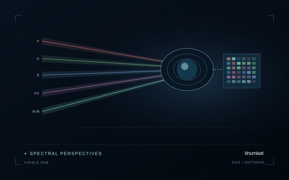
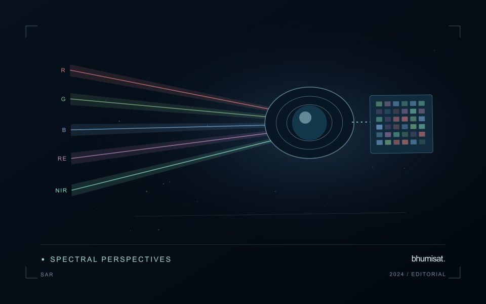
Synthetic aperture radar is an active observing technique: the instrument transmits microwave energy and measures the returned signal. Its image therefore represents a different interaction with the landscape from reflected visible or near-infrared sunlight. Radar can provide observations in conditions that limit optical imagery, but its response still depends on the instrument and scene. Backscatter should not be read as a universal moisture or vegetation score. Surface structure, water, roughness, geometry and the arrangement of scattering elements can contribute to the measured return.
Wavelength and polarisation influence which interactions are emphasised. The same agricultural field can change its radar response after rainfall, tillage, crop development or harvest, and several of those processes may occur together. The viewing direction and incidence angle also matter. A time series assembled without controlling these factors can contain differences that look like an environmental trend. Retain orbit, geometry, polarisation and processing metadata, and choose comparisons that are appropriate for the physical interpretation the application is intended to support.
Compare like with like before drawing conclusions
Radar images commonly contain speckle, a granular appearance associated with coherent measurement. Filtering or aggregation can make patterns easier to interpret, but it also changes spatial detail and statistical behaviour. Select processing around the reporting scale and evaluate its effects near boundaries. Terrain can create additional geometric challenges, including compressed or hidden areas in the radar view. A map should identify where the observation is difficult to interpret rather than filling every location with an equally confident result.
Complementary evidence helps distinguish plausible explanations for a radar change. Combine suitable optical observations, rainfall or management records and field measurements when they address the actual question. Validate a proposed model on independent locations and conditions, including cases where the expected relationship fails. A dark water surface in one setting does not establish a universal flood rule, because rough water, vegetation and built structures can produce different responses. Radar becomes valuable when its particular measurement physics is incorporated into a carefully defined monitoring workflow, with geometry and uncertainty remaining visible to the analyst and user.
The setting: Changing sandy shorelines
A shoreline is not always one fixed boundary that every observation measures in the same way. The visible water edge, a vegetation boundary and another mapped coastal indicator can represent different features. A monitoring programme should define its chosen shoreline consistently before comparing dates. Tidal conditions, wave state, seasonal beach changes and the geometry of the image can all influence the position recorded, even without a lasting change in the coast.
Spatial resolution and alignment determine the precision with which a boundary can be located. A sharply drawn line on a map should not imply more positional certainty than the observations support. Compare acquisitions under suitable conditions and retain the information needed to examine their differences. Mixed pixels, shadows and narrow coastal features may require manual review or an uncertainty zone rather than an automatic interpretation at every location.
Field validation should use the same shoreline definition as the image analysis and record when and how a position was measured. A visit under different water conditions may represent a different boundary even if its coordinates are accurate. Evaluate change over appropriate distances and periods, and avoid treating every small mapped displacement as erosion or deposition. A transparent product shows the observed positions, their dates and the uncertainty relevant to the decision being considered.
Maintain the geographic units of analysis
Many observation services summarise measurements within a field, management block, catchment, forest unit, or other mapped boundary. The meaning of that summary depends on whether the boundary accurately represents the unit being discussed. Start with a clear source for the geometry and record its date, coordinate reference, and intended use. A boundary drawn for visual orientation may require additional checking before it becomes a measurement unit.
Inspect overlaps, gaps, narrow fragments, and features that may have changed since mapping. A geometrically valid polygon can still describe an outdated operational unit. Ask the responsible team how divisions, mergers, new infrastructure, and management changes are recorded. Where pixels or reference measurements cross a boundary, define how they are assigned or excluded so that results remain comparable between analysts and processing runs.
Version the boundaries alongside the observations. If a unit changes, preserve a relationship between the previous and revised geometry rather than replacing the history without explanation. Comparisons through time should identify whether they use a constant spatial unit or the operational units valid at each date. This makes it easier to distinguish a change in the measured surface from a change introduced by the geography used to summarise it.
Design an evaluation that reflects deployment
A model evaluation should resemble the conditions in which the model will be used. Start by identifying which relationships the development data share: nearby locations, repeated observations of the same unit, common collection teams, or measurements from a single period. These relationships can make records less independent than they appear. An evaluation that ignores them may test the ability to recognise familiar conditions rather than the ability to operate in a new setting.
Choose a split strategy that matches the intended transfer. Holding out locations, seasons, operational units, or acquisition conditions can answer different questions. Document which question each split is designed to address, and keep the held-out evidence separate while selecting features and tuning the method. Repeatedly inspecting the same evaluation set to improve a model gradually makes that set part of development, even if it retains its original label.
Report results at a scale that is meaningful to the user. A strong average can hide poor performance for important subgroups or unusual conditions. Examine error patterns and retain examples of both successful and unsuccessful predictions. Where the evidence covers only a limited range of conditions, describe that range explicitly. The evaluation then becomes a practical guide to suitable use, further testing, and the collection of additional reference observations.
Bring the evidence back to the decision
Expansion should be guided by measured workload, visible quality conditions, and an understanding of which tasks require expert attention. Test the workflow under representative data volumes before treating a successful demonstration as evidence of operational capacity. Preserve a route for investigating individual observations even when most processing is automated. A scalable service keeps its results traceable and useful as it grows, with clear choices about where to automate, where to review, and where to invest in additional evidence.
Sources & further reading
Explore the bhumisat spacecraft concept and our vision towards 2030, or return to the journal.