A method that produces a plausible result has not automatically demonstrated that it works for its intended users. Validation requires a defined question, suitable reference evidence, and an evaluation design that reflects how the method will be used. This perspective examines which observations should be compared, how they should be sampled, and which errors matter in practice. It also considers the difference between evidence used to develop a method and evidence reserved for evaluating it. The objective is a test that can reveal weaknesses as well as confirm useful performance.
This working guide considers red edge sensing for vegetation studies across sediment-runoff catchments. The immediate decision is to connect sampling priorities across land and water. Useful reference evidence includes timed water samples, runoff context and land-cover observations. The case is an illustrative planning context, with assumptions to check against the actual sensor, landscape and project requirements.
Observe a transition, not a universal plant score
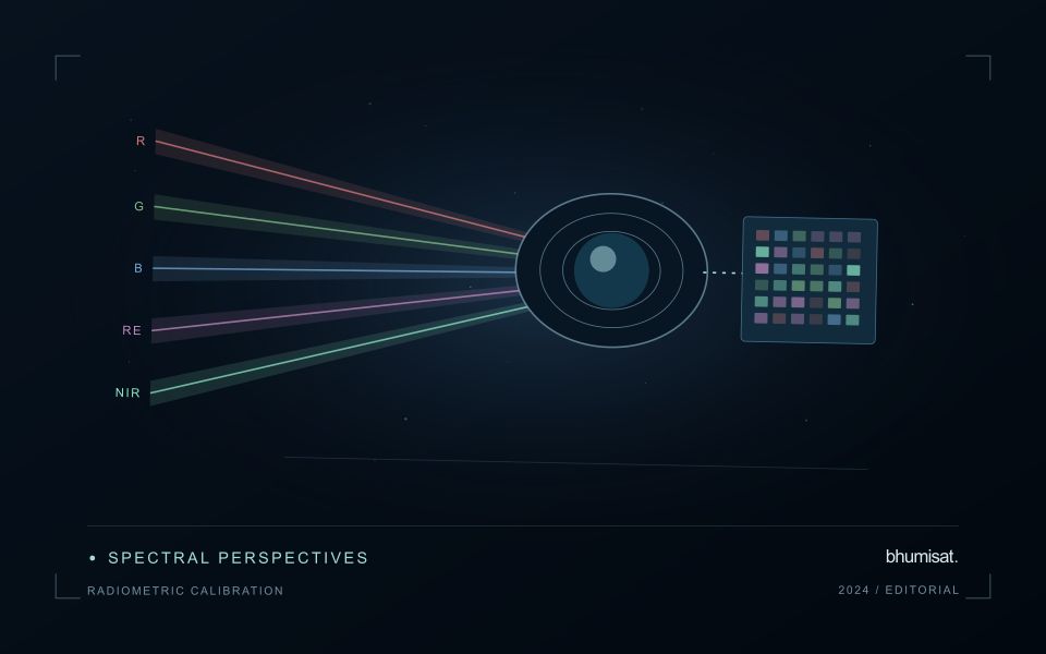
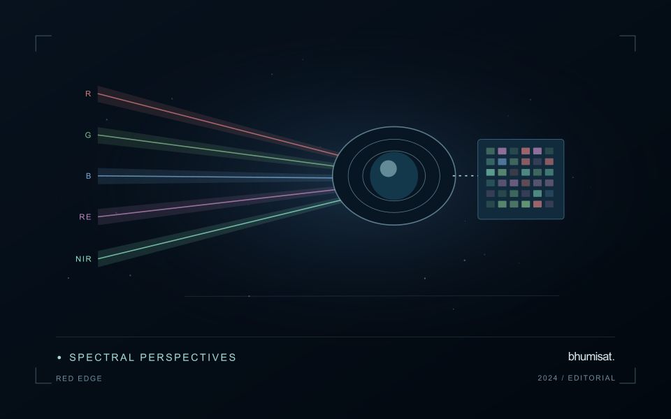
The Red Edge is a transition region in the spectral response of vegetation between visible red absorption and near-infrared reflectance. Measuring this region can add useful information to a vegetation study because different channels sample different parts of the transition. The phrase Red Edge is therefore a broad description rather than a complete instrument specification. A study needs the channel response, its bandwidth and its relationship to the other measurements used in the analysis. Those details influence what comparisons can be made reliably.
Leaf properties and the arrangement of leaves within a canopy both affect the signal reaching a satellite. The observed field also contains shadows, branches, soil and sometimes water or understory vegetation. Consequently, a relationship established with a leaf instrument cannot simply be assumed to hold at satellite-pixel scale. Scaling the interpretation requires observations that connect these levels. This distinction becomes especially important when the intended application concerns a specific biochemical parameter, because the image records a combined landscape response rather than an isolated leaf measurement.
Design the comparison around the instrument
Start an application study by identifying the information that an added Red Edge channel is expected to contribute. Compare that expectation with available data from established instruments and with a baseline method using fewer bands. Check whether any apparent improvement persists in independent fields and seasons. Use the same evaluation protocol for both methods. An instrument design decision should consider the improvement alongside calibration, alignment, signal quality and processing demands. More channels introduce more measurement opportunities and more relationships that must be understood.
For an ongoing service, retain enough metadata to trace every result to its source bands. A change in sensor, processing version or band selection can create a discontinuity in an otherwise plausible time series. Validate the transition rather than hiding it within a long historical chart. Clear documentation allows a user to distinguish a change in vegetation from a change in the observation system. Red Edge sensing becomes valuable when its additional spectral information can be linked to a defined application through repeatable measurements and independent evidence.
The setting: Sediment-runoff catchments
A catchment monitoring project connects land-cover patterns, drainage pathways and observations of receiving waters. These evidence streams operate at different spatial and temporal scales. A bare land patch or a bright water plume may be relevant to a sampling question, but an image alone does not establish that one caused the other. Define whether the task is mapping potential source areas, tracking a visible water pattern or evaluating a particular sediment-related variable.
Maintain suitable land and water masks and compare acquisitions with their rainfall and flow context where that information is available. Clouds can obscure the period of greatest interest, and conditions may change rapidly after runoff events. Land adjacency, shallow water and surface reflections can also affect optical interpretation. A useful monitoring record identifies the dates and valid areas supporting each observation instead of presenting a continuous causal story across missing measurements.
Field validation should collect water measurements with clear location, timing and sampling methods, alongside the evidence used to describe land conditions. Sampling only the most obvious plume may overlook other parts of the response or ordinary background variation. More specific source attribution needs an investigation designed for that claim. A practical first product can organise catchment observations and prioritise coordinated sampling, while keeping remotely observed associations distinct from explanations established through additional measurements.
Use observation labels with consistent meanings
A reference label should describe an observation that another person could recognise or reproduce. Broad terms such as good, damaged, or unusual can conceal substantial differences between collection teams. Begin by defining the feature or condition being recorded, the observation unit, and the evidence needed to assign a label. Where possible, distinguish a direct measurement from an interpretation made by the observer.
Provide a short collection guide with examples, boundary cases, and a way to record uncertainty. Train observers using shared cases before relying on independently collected labels. If two observers disagree, preserve the disagreement long enough to understand its cause. It may reveal an unclear definition, a genuinely ambiguous condition, a difference in observation scale, or a problem in matching the reference record to the remote measurement.
Retain the context that makes the label interpretable. Location, time, collection method, observer role, and relevant surface conditions can be essential for later review. Changes to the label scheme should be documented and related to earlier versions where a defensible correspondence exists. Consistent labels do not eliminate uncertainty, but they make it possible to investigate disagreement, evaluate analytical methods, and identify where better definitions or additional measurements would improve the evidence.
Check spatial alignment before comparison
A comparison between images, channels, maps, or field measurements assumes that the observations refer to the same locations at a suitable level of precision. Small alignment errors can become especially important near boundaries or narrow features. Before interpreting differences, inspect whether identifiable, stable features agree between the sources. A common coordinate reference is necessary for many workflows, but it does not by itself demonstrate accurate alignment.
Use control features that are appropriate for the observation scale and remain stable across the comparison period. Evaluate alignment in more than one part of the area, because a single location cannot reveal spatially varying distortion. Record the method used to estimate any correction and retain independent features for checking the corrected result. Where surfaces have genuinely changed, avoid using those changes as evidence of an alignment error.
Propagate the implications of remaining misalignment into the analysis. A workflow may exclude boundary pixels, summarise at a broader scale, or qualify interpretations for small features. The choice should follow the application rather than a preference for visually smooth output. Preserve both the original and corrected geographic references, and document resampling decisions so that future users can understand how measurements were moved onto a common spatial framework.
Bring the evidence back to the decision
The validation record should explain the population represented by the test, the reference observations used, and the limitations of the comparison. Report meaningful errors alongside useful successes, and retain examples that challenge the method. Treat wider deployment as a new opportunity to evaluate transfer across relevant conditions. A well-designed validation programme gives users a defensible basis for deciding where the method is useful, where additional evidence is needed, and where another approach may be appropriate.
Sources & further reading
Explore the bhumisat spacecraft concept and our vision towards 2030, or return to the journal.