Remote observations show patterns, while practical decisions depend on explaining what those patterns could mean. Interpretation therefore requires more than locating a high or low value on a map. A useful analysis considers the timing of the observation, the physical processes that influence the measurement, and the information available from complementary sources. This perspective separates an observed signal from a proposed explanation and from an action recommended to a user. Keeping those stages distinct makes it easier to investigate alternative causes, communicate ambiguity, and choose a proportionate next step.
This working guide considers radiometric calibration and reflectance consistency in rubber estate blocks. The immediate decision is to plan inspections around canopy transitions. Useful reference evidence includes leafing stage, tree age and block management records. The case is an illustrative planning context, with assumptions to check against the actual sensor, landscape and project requirements.
The setting: Rubber estate blocks
Rubber estates contain stands of different ages, canopy structures and management histories. Seasonal leaf changes can also influence the image record, so a shift in vegetation response should not automatically be treated as deterioration. Interpret observations with a local calendar and a clear definition of the target variable. The first question is whether the service concerns plantation cover, stand development, management activity or a more specific operational indicator.
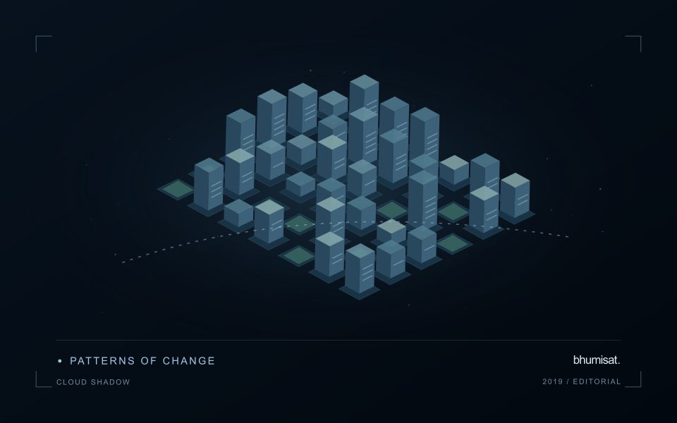
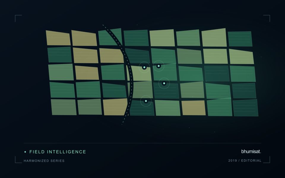
Build a block inventory that separates mature stands, young plantings, open areas and other land covers where possible. Compare observations from suitable periods and inspect whether cloud, shadow or haze has affected the available measurements. Roads, drainage lines and conservation vegetation may require separate treatment. A numerical difference between blocks is more informative when the report also shows their stand context and the actual dates on which usable observations were collected.
Validation should record tree age, canopy condition, leafing stage and relevant recent operations at identified locations. Commercial output records may be influenced by factors beyond the remotely observed canopy, so any relationship with production must be tested for the intended use. Field staff should be able to distinguish a satellite-derived inspection priority from a confirmed explanation. Retaining the outcome of follow-up visits helps reveal both useful alerts and situations where the mapped pattern had an ordinary management explanation.
Define the quantity that the instrument records
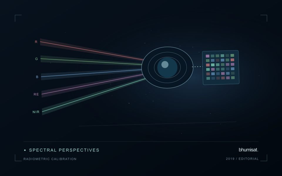
Radiometric calibration establishes a documented relationship between an instrument's recorded output and the physical quantity it is intended to represent. A stored pixel value may be a digital number, a scaled radiance or reflectance value, or another processed representation. Those alternatives should not be treated as interchangeable. The calibration chain explains how the recorded signal becomes an interpretable measurement and which corrections have already been applied. Understanding that chain is essential before comparing dates, combining bands or transferring a model between instruments.
Instrument response can vary across detectors, channels and operating conditions. Calibration therefore concerns more than selecting one conversion coefficient. A study may need to consider offsets, response differences, noise, saturation and changes in behaviour over time. The appropriate characterisation depends on the instrument and its intended use. For a future payload concept, these are requirements to investigate rather than capabilities established by an attractive render. The presence of a multispectral camera alone does not demonstrate that its channels produce consistent, quantitatively comparable observations.
Track consistency through the complete chain
At the product level, begin with the supplier's definitions and metadata. Check scale factors, additive offsets, fill values and valid ranges before deriving an index or statistical summary. Preserve the processing version so that an output can be reproduced later. Inspect whether extreme values correspond to real surfaces or to invalid observations. When a dataset is updated, compare representative old and new results rather than assuming that a familiar file name guarantees an unchanged numerical meaning throughout the archive.
Validation should cover the full chain that supports the stated application. A stable response in a laboratory test is valuable evidence, while operational imagery introduces additional effects from atmosphere, geometry and scene complexity. Use independent references suited to the measurement scale and report the relevant uncertainty. Maintain a record of corrections and their limitations when delivering results to users. A traceable radiometric workflow supports meaningful comparisons and helps separate a change in the observation system from a change in the landscape that a monitoring service is trying to describe.
Translate the decision into observation requirements
Start with the decision that the information is intended to support. Describe the geographic unit, the time available for acting, and the consequence of an incorrect interpretation. A requirement such as detecting an unusual pattern across management blocks is different from identifying its cause. Keeping that distinction explicit helps a team select measurements that are relevant to the application and prevents later evaluation from drifting towards whatever result happens to be easiest to demonstrate.
Build a compact requirements matrix linking each decision to the evidence needed, the proposed observation source, and an acceptance condition. Include geographic accuracy, temporal relevance, quality screening, and the context required for interpretation. The matrix should also identify the evidence used to justify each requirement. An engineering preference or a convenient data source can inform a study, but neither should silently replace a documented information need.
Review the matrix with the people who will use the result. Ask how their response would change when information is delayed, incomplete, or uncertain. Record unresolved requirements as questions for a pilot rather than converting them into confident specifications. This produces a practical framework for comparing technical options, designing tests, and explaining why an observation is useful to the intended workflow.
Plan the evidence needed for calibration
Calibration connects an instrument's recorded response with a measurement that can be interpreted consistently. Begin by identifying which aspects of the response matter to the application: variation across channels, changes with operating conditions, geometric alignment, or differences between repeated observations. A calibration plan should state the quantities being assessed and the evidence needed to determine whether the response is sufficiently characterised for the intended use.
Design tests around controlled and documented conditions. Record the reference source, instrument configuration, exposure settings, temperature conditions, and processing applied to the measurements. Repeat suitable observations to investigate variability and distinguish a consistent response from a single favourable result. The reference itself has limitations, so preserve its characterisation and avoid assuming that every difference originates in the instrument under evaluation.
Connect calibration activities with the expected operating environment and processing chain. A correction that works under one test condition may require further evidence before being applied elsewhere. Define how calibration parameters are versioned, checked, and associated with the observations they support. Include a plan for recognising drift or other changes that could affect interpretation. The outcome should be an instrument response supported by traceable evidence, together with acceptance criteria that remain relevant to the application.
Bring the evidence back to the decision
A strong interpretation states what was observed, which explanations remain plausible, and what additional evidence would help distinguish them. Avoid presenting a convenient label as a confirmed cause when the measurements support only a broader pattern. Connect the proposed next step to the significance of the decision and the confidence available. This creates an interpretation that a field team, analyst, or project partner can examine, challenge, and improve as further observations become available.
Sources & further reading
Explore the bhumisat spacecraft concept and our vision towards 2030, or return to the journal.