A workflow that succeeds on a small study area may encounter different constraints when the number of observations, locations, or users increases. Scaling requires attention to processing capacity, data organisation, reference coverage, and the effort needed to review results. This perspective looks beyond whether a calculation can run on a larger dataset. It asks whether the complete service can preserve its meaning, quality, and delivery commitments as its scope expands. The objective is a design that identifies bottlenecks early and increases throughput without silently weakening the evidence available to users.
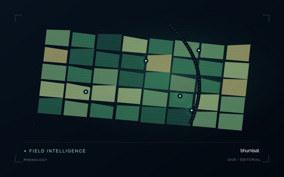
This working guide considers how pointing and motion affect satellite imagery along transport corridor landscapes. The immediate decision is to locate corridor sections for inspection. Useful reference evidence includes dated corridor observations and consistent feature boundaries. The case is an illustrative planning context, with assumptions to check against the actual sensor, landscape and project requirements.
The setting: Transport corridor landscapes
A transport corridor is a narrow network embedded in changing vegetation, settlements, water and other land uses. The relevant observation might concern vegetation near a route, a visible land-cover change or a section that needs a closer inspection. Define the corridor width and feature of interest before analysis. A satellite-derived surface pattern does not by itself establish the engineering condition or operational safety of the infrastructure within that area.
Narrow features are particularly sensitive to image resolution and geometric alignment. A small offset can move a measurement from the corridor into adjacent land, while shadows or seasonal vegetation can alter a comparison between dates. Use a spatial support suitable for the intended question and review sections where surrounding surfaces dominate the signal. Retain observation quality and acquisition timing so that users know which sections have current evidence and which remain uncertain.
Field validation should locate the observed feature and document the area represented by each inspection record. Include ordinary corridor sections as well as locations ranked unusual by the analysis. The purpose is to test whether the mapped pattern helps identify a relevant condition, not merely whether it produces a visually distinctive alert. More specific engineering conclusions require appropriate measurements and expertise, while a transparent observation record can make the selection of inspection sites more systematic.
Separate the different pointing requirements
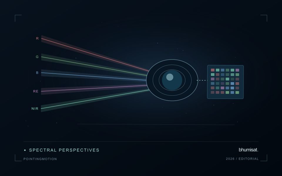
A camera can point near its intended target while still producing an image with poor geometry or blur. Pointing accuracy describes how closely the spacecraft achieves a commanded orientation. Pointing knowledge describes how well that orientation is estimated. Stability concerns changes over a relevant interval, including the detector integration period. These quantities serve different purposes and should be specified separately with a clear reference frame and time basis.
Orientation estimates combine information from sensors such as gyroscopes, Sun sensors and star trackers, depending on the architecture. Actuators then change or maintain the attitude. Reaction wheels exchange angular momentum with the spacecraft, while magnetic torquers interact with Earth's magnetic field and may support momentum management. Their suitability depends on the orbit, operating modes and disturbance environment. A component's advertised accuracy does not automatically become the pointing performance of the integrated spacecraft.
Evaluate the complete image motion budget
Ground features move across a detector because the spacecraft travels along its orbit and may rotate during imaging. Exposure time, scan timing and any motion compensation must be consistent with that movement. Residual motion during integration spreads signal across pixels and reduces contrast. High frequency vibration can produce a different image effect from slow drift, so one average attitude error may conceal an important problem.
Build an image motion budget that includes control behavior, structural response, actuator disturbances and timing uncertainties. Consider the mechanical path between attitude sensors and the optical payload: a flexible interface can change their relative alignment. Thermal distortion can also alter boresight alignment over an orbit. Test realistic operating combinations, including wheel speeds and other mechanisms that may run during an exposure, and assess whether laboratory support equipment affects the measurement.
Geometric processing uses orbit information, attitude knowledge, timing and an Earth model to locate observations. Ground control and image matching can improve some errors, but processing cannot always restore information lost to blur. For repeat observations, test relative registration as well as absolute location. Report residual errors across the field and across relevant operating conditions. A useful requirement links a user consequence, such as registration between spectral bands, to a measurable spacecraft or payload behavior and a verification method. This keeps pointing discussions connected to the quality of the delivered imagery.
Maintain the geographic units of analysis
Many observation services summarise measurements within a field, management block, catchment, forest unit, or other mapped boundary. The meaning of that summary depends on whether the boundary accurately represents the unit being discussed. Start with a clear source for the geometry and record its date, coordinate reference, and intended use. A boundary drawn for visual orientation may require additional checking before it becomes a measurement unit.
Inspect overlaps, gaps, narrow fragments, and features that may have changed since mapping. A geometrically valid polygon can still describe an outdated operational unit. Ask the responsible team how divisions, mergers, new infrastructure, and management changes are recorded. Where pixels or reference measurements cross a boundary, define how they are assigned or excluded so that results remain comparable between analysts and processing runs.
Version the boundaries alongside the observations. If a unit changes, preserve a relationship between the previous and revised geometry rather than replacing the history without explanation. Comparisons through time should identify whether they use a constant spatial unit or the operational units valid at each date. This makes it easier to distinguish a change in the measured surface from a change introduced by the geography used to summarise it.
Deliver quality flags that users can interpret
Quality information should describe the condition of an observation in terms that remain useful through the workflow. A single valid or invalid label may be sufficient for some calculations, but operational users often need to know why an observation was qualified. Distinguish acquisition limitations, processing failures, uncertain reference matches, and conditions that make interpretation ambiguous. These categories point towards different responses and should not be merged without a clear purpose.
Define a small, documented set of flags with stable meanings. Record whether a flag applies to a complete scene, a geographic unit, an individual measurement, or a derived result. A unit containing a mixture of qualified and unqualified observations may also require a coverage measure. Include the rule used to combine flags when summarising data so that a favourable average does not conceal a substantial fraction of unusable input.
Test the flags with the people receiving the product. Ask what they would do differently for each state and whether the terminology supports that choice. Keep the original flags available even if the interface presents a simpler summary. When flag definitions change, version the rules and review their effects on historical comparisons. Useful quality communication makes the condition of the evidence visible at the moment when a user decides how much confidence to place in the result.
Bring the evidence back to the decision
Expansion should be guided by measured workload, visible quality conditions, and an understanding of which tasks require expert attention. Test the workflow under representative data volumes before treating a successful demonstration as evidence of operational capacity. Preserve a route for investigating individual observations even when most processing is automated. A scalable service keeps its results traceable and useful as it grows, with clear choices about where to automate, where to review, and where to invest in additional evidence.
Sources & further reading
Explore the bhumisat spacecraft concept and our vision towards 2030, or return to the journal.