An analytical result becomes operational information only when the receiving team can understand it and use it within existing responsibilities. Handoffs often fail because assumptions that were obvious to the analyst are absent from the delivered product. This perspective considers the information needed at that boundary: acquisition time, processing status, geographic scope, quality qualifications, and the action expected from the recipient. It also asks how corrections and feedback should return to the producing team. A dependable handoff creates a shared understanding of the result, rather than merely transferring a file.
This working guide considers how pointing and motion affect satellite imagery during payload integration studies. The immediate decision is to plan integrated payload test sequences. Useful reference evidence includes measured instrument responses and traceable test configurations. The case is an illustrative planning context, with assumptions to check against the actual sensor, landscape and project requirements.
Separate the different pointing requirements
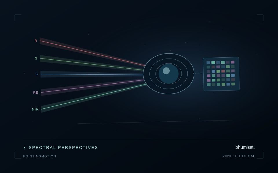
A camera can point near its intended target while still producing an image with poor geometry or blur. Pointing accuracy describes how closely the spacecraft achieves a commanded orientation. Pointing knowledge describes how well that orientation is estimated. Stability concerns changes over a relevant interval, including the detector integration period. These quantities serve different purposes and should be specified separately with a clear reference frame and time basis.
Orientation estimates combine information from sensors such as gyroscopes, Sun sensors and star trackers, depending on the architecture. Actuators then change or maintain the attitude. Reaction wheels exchange angular momentum with the spacecraft, while magnetic torquers interact with Earth's magnetic field and may support momentum management. Their suitability depends on the orbit, operating modes and disturbance environment. A component's advertised accuracy does not automatically become the pointing performance of the integrated spacecraft.
Evaluate the complete image motion budget
Ground features move across a detector because the spacecraft travels along its orbit and may rotate during imaging. Exposure time, scan timing and any motion compensation must be consistent with that movement. Residual motion during integration spreads signal across pixels and reduces contrast. High frequency vibration can produce a different image effect from slow drift, so one average attitude error may conceal an important problem.
Build an image motion budget that includes control behavior, structural response, actuator disturbances and timing uncertainties. Consider the mechanical path between attitude sensors and the optical payload: a flexible interface can change their relative alignment. Thermal distortion can also alter boresight alignment over an orbit. Test realistic operating combinations, including wheel speeds and other mechanisms that may run during an exposure, and assess whether laboratory support equipment affects the measurement.
Geometric processing uses orbit information, attitude knowledge, timing and an Earth model to locate observations. Ground control and image matching can improve some errors, but processing cannot always restore information lost to blur. For repeat observations, test relative registration as well as absolute location. Report residual errors across the field and across relevant operating conditions. A useful requirement links a user consequence, such as registration between spectral bands, to a measurable spacecraft or payload behavior and a verification method. This keeps pointing discussions connected to the quality of the delivered imagery.
The setting: Payload integration studies
A payload integration study examines how an observation instrument behaves as part of a wider spacecraft concept. The camera, optics, electronics, structure and processing path cannot be assessed solely as independent catalogue items. Begin by identifying the measurements the complete system must support and the conditions under which they should be demonstrated. A component description can inform the design, but it does not establish the performance of an integrated imaging chain.
Test planning should record the hardware configuration, operating settings, reference targets and environmental conditions relevant to each measurement. Changes between tests need to remain traceable so that an apparent improvement is not confused with a different test setup. Spectral alignment, image geometry and radiometric consistency may interact with mechanical or thermal behaviour. The investigation should identify those relationships rather than relying only on whether an acquired test image looks visually sharp or colourful.
Acceptance criteria should connect instrument measurements with the needs of the intended application. Retain uncertainties, unsuccessful tests and design changes as part of the evidence used to evaluate progress. A laboratory demonstration under one condition should not be described as flight-qualified capability without the necessary additional work. A useful result at this stage is an auditable account of integrated behaviour, the remaining measurement questions and the next tests needed to assess the proposed payload architecture.
Plan the evidence needed for calibration
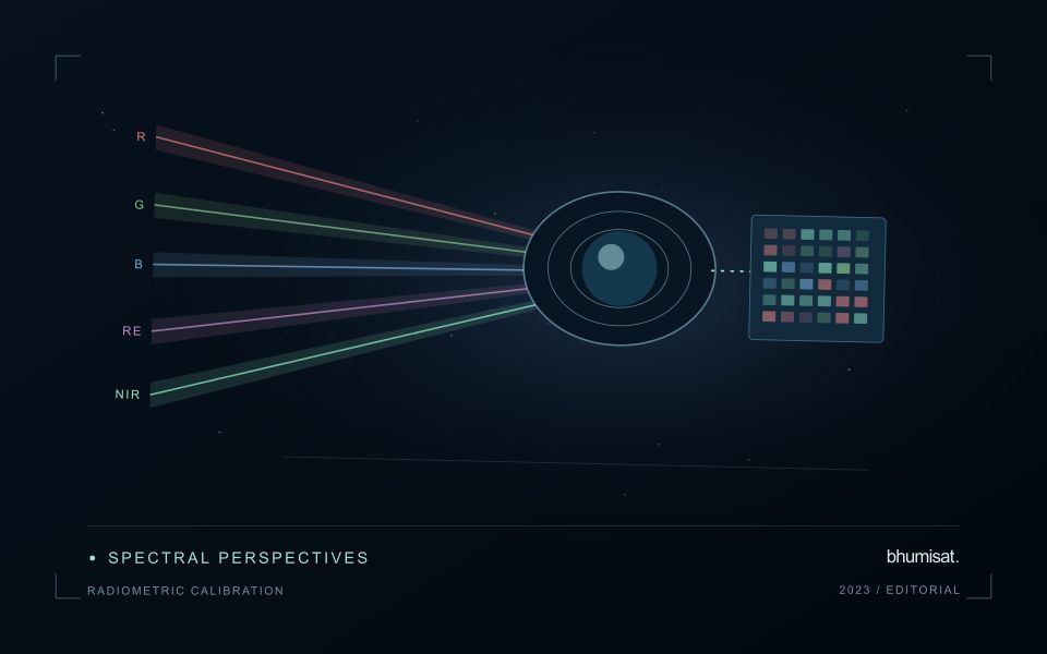
Calibration connects an instrument's recorded response with a measurement that can be interpreted consistently. Begin by identifying which aspects of the response matter to the application: variation across channels, changes with operating conditions, geometric alignment, or differences between repeated observations. A calibration plan should state the quantities being assessed and the evidence needed to determine whether the response is sufficiently characterised for the intended use.
Design tests around controlled and documented conditions. Record the reference source, instrument configuration, exposure settings, temperature conditions, and processing applied to the measurements. Repeat suitable observations to investigate variability and distinguish a consistent response from a single favourable result. The reference itself has limitations, so preserve its characterisation and avoid assuming that every difference originates in the instrument under evaluation.
Connect calibration activities with the expected operating environment and processing chain. A correction that works under one test condition may require further evidence before being applied elsewhere. Define how calibration parameters are versioned, checked, and associated with the observations they support. Include a plan for recognising drift or other changes that could affect interpretation. The outcome should be an instrument response supported by traceable evidence, together with acceptance criteria that remain relevant to the application.
Prioritise alerts using evidence and consequence
An alert is a request for attention, so its design should consider both the evidence available and the cost of responding. Begin by distinguishing a measured change, a proposed interpretation, and the action expected from the recipient. A large numerical difference is not automatically the most urgent case. The significance of the location, the age of the observation, the confidence in the interpretation, and the consequences of delay can all influence priority.
Create a review queue with enough context to support consistent decisions. Useful information can include the supporting dates, quality qualifications, previous observations, geographic unit, and the reason the case entered the queue. Define when an alert can be closed, escalated, or held for another observation. A documented rule is easier to improve than an informal practice that depends entirely on the memory of the operator reviewing the result.
Collect feedback from inspections and operational responses. Record alerts that led to a useful finding, alerts that required no action, and important conditions that the system failed to flag. Review these outcomes across different settings rather than relying only on a total count of alerts. The objective is a queue that directs limited attention towards meaningful decisions, while generating evidence for adjusting thresholds, improving context, and reducing repeated sources of unnecessary work.
Bring the evidence back to the decision
A successful handoff leaves the recipient with a clear result, sufficient context, and a practical route for raising questions. Test the delivery with the people who will use it, including how they respond when observations are missing or qualified. Capture their feedback as evidence for improving the product. The most useful delivery format is the one that preserves the relevant technical meaning while fitting the decisions, time constraints, and responsibilities of its intended audience.
Sources & further reading
Explore the bhumisat spacecraft concept and our vision towards 2030, or return to the journal.