A useful observation programme begins with a decision that somebody can act on. Before selecting imagery or instruments, define the area of interest, the people responsible for inspecting it, and the time available for a response. This planning perspective connects remote measurements with the practical questions that shape a survey or monitoring service. The aim is to identify which observations would change a decision, how supporting evidence would be collected, and what should happen when information is incomplete. A clear plan makes later technical choices easier to assess against an operational purpose.
This working guide considers connecting drone surveys with satellite observations on mountain forest slopes. The immediate decision is to select terrain-aware forest inspection sites. Useful reference evidence includes slope setting, canopy observations and reliable sample locations. The case is an illustrative planning context, with assumptions to check against the actual sensor, landscape and project requirements.
Give each platform a clear role
Drone surveys and satellites observe the same landscape at different scales and with different constraints. A drone can collect detailed local observations at a selected time, while satellites provide repeated coverage over larger regions. Combining them is useful when the local survey answers a specific question: checking crop rows, describing canopy gaps, measuring a surface, or supporting reference interpretation. Define that role before planning the flight. A detailed orthomosaic does not automatically become accurate reference data merely because its pixels are small.
Radiometric consistency requires attention to exposure settings, sensor response, illumination, and calibration targets where appropriate. Geometric quality depends on camera calibration, flight geometry, image overlap, tie points, and the accuracy of positioning and ground control. Surface reconstruction can struggle over water, moving vegetation, uniform textures, or repeated patterns. Keep independent checkpoints separate from control points used to fit the reconstruction, and evaluate horizontal and vertical accuracy against the requirements of the intended measurement.
Compare like with like
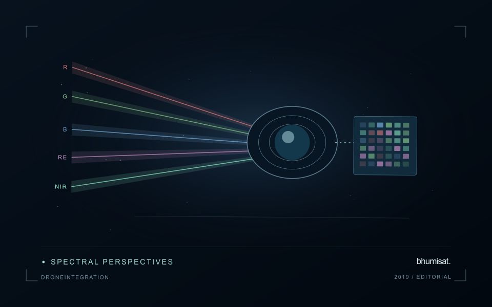
Align coordinate systems, vertical datums where relevant, and acquisition times before comparing products. A field can change after irrigation, rainfall, harvest, or a different sun angle, so a convenient date may not represent the satellite overpass. Satellite bands also have different spectral response functions from a drone camera. Matching band names does not guarantee that their reflectance values are equivalent. Describe these differences and select a comparison that the measurements can support.
Aggregate drone observations to the satellite pixel footprint or another justified analysis unit rather than simply sharpening the satellite grid. Include edge effects, positional uncertainty, and spatial heterogeneity in the comparison. A satellite pixel may mix trees, soil, shade, and roads that the drone resolves individually. Sample drone sites across the conditions present in the larger region; surveying only easy access sites can bias a calibration model. Keep training and evaluation locations independent when drone products support machine learning. Deliver the local survey with flight dates, processing settings, calibration records, accuracy checks, and known gaps. The combined workflow should make the relationship between local detail and regional inference explicit, including where the drone sample does not justify extrapolation.
The setting: Mountain forest slopes
A mountain forest combines canopy complexity with strong changes in slope, aspect and illumination. Locations that contain similar vegetation may appear different because they are observed under different lighting conditions. A monitoring design should therefore consider terrain alongside its ecological question. Define whether it concerns cover change, disturbance or a particular forest parameter, and establish comparison units that do not confuse a shadowed slope with a different type or condition of forest.
Image selection and processing should retain the information needed to examine these effects. Cloud, terrain shadow and changing viewing geometry can limit the usable record in different ways. A detailed elevation model may help describe the setting, but its resolution and alignment also need consideration. Review boundary areas and narrow valleys carefully, where mixed surfaces or small spatial offsets can have a large influence on an apparent change.
Field observations should represent the range of terrain settings in which the monitoring result will be used. Convenient valley access points may not characterise conditions on upper slopes. Record the location, slope context, canopy structure and date of each sample, along with uncertainty in locating it. A successful interpretation should remain defensible across the relevant terrain range. Where that has not been demonstrated, present the observation as a terrain-aware inspection lead rather than a fully validated forest measurement.
Locate the uncertainty that matters to the decision
An uncertainty budget is a practical description of where a result could become unreliable. Begin with the observation chain: acquisition, calibration, geographic matching, reference measurements, feature calculation, modelling, and delivery. Identify the assumptions at each stage and ask which could materially change the interpretation. The purpose is not to assign a precise number to every limitation. It is to locate the sources that deserve attention for the intended decision.
Separate limitations that can be measured from those that currently require a qualitative description. Repeated measurements may help characterise variability, while comparisons with independent references can reveal systematic differences. Some uncertainties interact, so combining individual error estimates without examining their relationships can produce a misleading impression of precision. Keep the method of assessment visible and avoid treating an unexamined assumption as though it were a negligible contribution.
Use the budget to prioritise further work. The largest visible source of variation is not always the one whose reduction would most improve the decision. Consider which additional observation, test, or contextual record would change confidence in an actionable way. Revisit the budget when the application, observation source, or deployment conditions change. This turns uncertainty analysis into a guide for improving the workflow rather than a qualification added only after the result has been delivered.
Plan the evidence needed for calibration
Calibration connects an instrument's recorded response with a measurement that can be interpreted consistently. Begin by identifying which aspects of the response matter to the application: variation across channels, changes with operating conditions, geometric alignment, or differences between repeated observations. A calibration plan should state the quantities being assessed and the evidence needed to determine whether the response is sufficiently characterised for the intended use.
Design tests around controlled and documented conditions. Record the reference source, instrument configuration, exposure settings, temperature conditions, and processing applied to the measurements. Repeat suitable observations to investigate variability and distinguish a consistent response from a single favourable result. The reference itself has limitations, so preserve its characterisation and avoid assuming that every difference originates in the instrument under evaluation.
Connect calibration activities with the expected operating environment and processing chain. A correction that works under one test condition may require further evidence before being applied elsewhere. Define how calibration parameters are versioned, checked, and associated with the observations they support. Include a plan for recognising drift or other changes that could affect interpretation. The outcome should be an instrument response supported by traceable evidence, together with acceptance criteria that remain relevant to the application.
Bring the evidence back to the decision
The practical outcome should be a short observation plan that another team can follow. It should name the decision, the required evidence, the responsible roles, and the conditions that trigger a field visit or further analysis. Keep the plan small enough to test, then revise it using the results of real inspections. A useful monitoring workflow improves because its assumptions are examined systematically, and its observations remain connected to decisions throughout the process.
Sources & further reading
Explore the bhumisat spacecraft concept and our vision towards 2030, or return to the journal.