A useful observation programme begins with a decision that somebody can act on. Before selecting imagery or instruments, define the area of interest, the people responsible for inspecting it, and the time available for a response. This planning perspective connects remote measurements with the practical questions that shape a survey or monitoring service. The aim is to identify which observations would change a decision, how supporting evidence would be collected, and what should happen when information is incomplete. A clear plan makes later technical choices easier to assess against an operational purpose.
This working guide considers viewing geometry and brdf effects across mine restoration areas. The immediate decision is to target restoration follow-up visits. Useful reference evidence includes treatment records, surface condition and representative vegetation checks. The case is an illustrative planning context, with assumptions to check against the actual sensor, landscape and project requirements.
The setting: Mine restoration areas
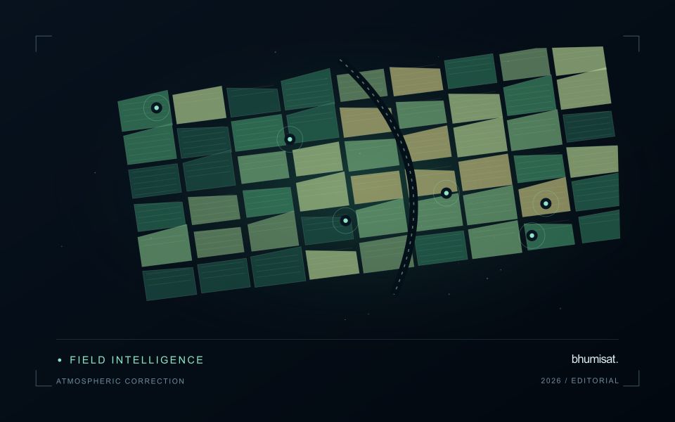
A mine restoration area can contain reshaped ground, drainage features, exposed material, planted vegetation and naturally developing cover. A remote-sensing product should distinguish these components and identify the outcome it is intended to assess. Mapping the extent of visible vegetation is different from evaluating restoration success, soil condition or stability. An increase in greenness may be useful evidence, but it cannot establish all of those outcomes on its own.
Treatment boundaries and dated operation records help interpret the image sequence. Compare suitable seasonal periods and account for the influence of soil background, terrain illumination and remaining industrial surfaces. Some planting patches may be too small to separate reliably in the chosen imagery. Retain observation dates, quality masks and the area contributing to each summary so that the result does not imply finer detail or more continuous monitoring than the data provide.
Field validation should record vegetation establishment, composition and the surface attributes required by the restoration objective. Include different treatment areas and apparently successful locations as well as obvious gaps. A model for a particular outcome needs reference measurements and evaluation matched to that claim. A practical first service can provide an auditable record of visible cover development and inspection priorities, while more comprehensive conclusions combine that record with the field evidence needed to assess the intended restoration performance.
The observed surface has a direction-dependent response
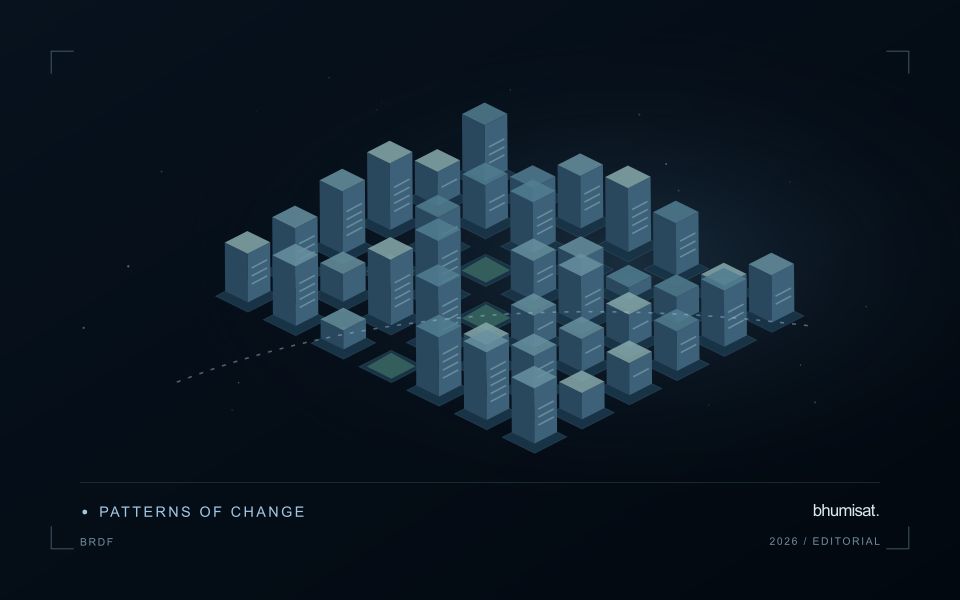
A surface does not necessarily reflect incoming light equally in every direction. Its measured brightness can change as the positions of the Sun, surface and sensor change, even when the surface itself is similar. The bidirectional reflectance distribution function provides a framework for describing this directional behaviour. In practical image analysis, the relevant lesson is that a difference between observations may contain a geometry effect as well as a real surface change. Canopy structure, shadows and surface roughness can all influence that relationship.
The magnitude and pattern of a geometry effect depend on the landscape and spectral measurement. A row crop, closed forest and exposed soil need not behave in the same way. Terrain introduces another layer because slope and aspect alter local illumination. A simple brightness adjustment is not automatically an adequate solution. A workflow should first identify the type of comparison it needs and whether the available product already includes a relevant normalisation. Applying an additional correction without understanding prior processing can create a new inconsistency.
Normalise geometry with a clear purpose
Geometry normalisation uses a model or adjustment to express observations under a more consistent reference condition. It is an approximation designed for a defined purpose, and its performance should be checked rather than assumed. Keep the input geometry, model assumptions and processing version where they are available. Compare representative surfaces before and after the adjustment. A useful test examines whether the correction reduces systematic variation in stable areas while preserving changes that are supported independently by management records or field observations.
For an agricultural service, the importance of this effect depends on the size of the change being interpreted. A subtle trend can be more sensitive to residual geometry variation than a major harvest event. Evaluate whether an apparent improvement in a time series survives across seasons and fields, including those with different canopy arrangements. Retain a clear explanation of what has been normalised and what remains uncertain. Viewing geometry becomes manageable when it is treated as part of the measurement context instead of being attributed silently to crop condition or land-cover change.
Deliver quality flags that users can interpret
Quality information should describe the condition of an observation in terms that remain useful through the workflow. A single valid or invalid label may be sufficient for some calculations, but operational users often need to know why an observation was qualified. Distinguish acquisition limitations, processing failures, uncertain reference matches, and conditions that make interpretation ambiguous. These categories point towards different responses and should not be merged without a clear purpose.
Define a small, documented set of flags with stable meanings. Record whether a flag applies to a complete scene, a geographic unit, an individual measurement, or a derived result. A unit containing a mixture of qualified and unqualified observations may also require a coverage measure. Include the rule used to combine flags when summarising data so that a favourable average does not conceal a substantial fraction of unusable input.
Test the flags with the people receiving the product. Ask what they would do differently for each state and whether the terminology supports that choice. Keep the original flags available even if the interface presents a simpler summary. When flag definitions change, version the rules and review their effects on historical comparisons. Useful quality communication makes the condition of the evidence visible at the moment when a user decides how much confidence to place in the result.
Validate land-cover transitions
A mapped change should describe a transition between meaningful surface states, not merely a difference between two classifications. Begin by defining the land-cover categories, the geographic unit, and the kinds of transition relevant to the application. Categories should be interpretable in the observations available at each date. A distinction that cannot be recognised consistently can create apparent change even when the underlying surface remains similar.
Evaluate the observations supporting both sides of the transition. Differences in acquisition conditions, geographic alignment, seasonal vegetation, shadows, or class definitions can influence the result. Review stable locations alongside apparent changes, and retain the source imagery or other evidence needed to investigate ambiguous cases. Where multiple changes occur within a geographic unit, describe how the workflow represents mixtures rather than forcing a single label that conceals important variation.
Use reference evidence that reflects the timing and scale of the claimed transition. A recent inspection may confirm the current surface without establishing when a previous condition changed. Historical imagery, dated records, and complementary observations can strengthen that sequence where available. Report uncertainty in the transition itself, including ambiguous starting or ending states. This produces a change product that users can examine as a documented account of land-cover evolution rather than an unexplained set of coloured differences.
Bring the evidence back to the decision
The practical outcome should be a short observation plan that another team can follow. It should name the decision, the required evidence, the responsible roles, and the conditions that trigger a field visit or further analysis. Keep the plan small enough to test, then revise it using the results of real inspections. A useful monitoring workflow improves because its assumptions are examined systematically, and its observations remain connected to decisions throughout the process.
Sources & further reading
Explore the bhumisat spacecraft concept and our vision towards 2030, or return to the journal.