Remote observations show patterns, while practical decisions depend on explaining what those patterns could mean. Interpretation therefore requires more than locating a high or low value on a map. A useful analysis considers the timing of the observation, the physical processes that influence the measurement, and the information available from complementary sources. This perspective separates an observed signal from a proposed explanation and from an action recommended to a user. Keeping those stages distinct makes it easier to investigate alternative causes, communicate ambiguity, and choose a proportionate next step.
This working guide considers spectral band alignment and common grids during payload integration studies. The immediate decision is to plan integrated payload test sequences. Useful reference evidence includes measured instrument responses and traceable test configurations. The case is an illustrative planning context, with assumptions to check against the actual sensor, landscape and project requirements.
A multiband value should refer to the same ground
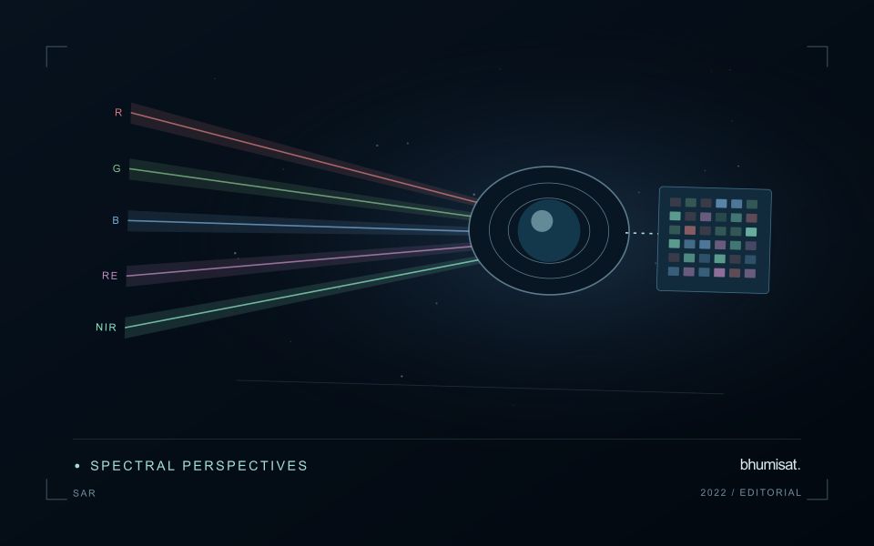
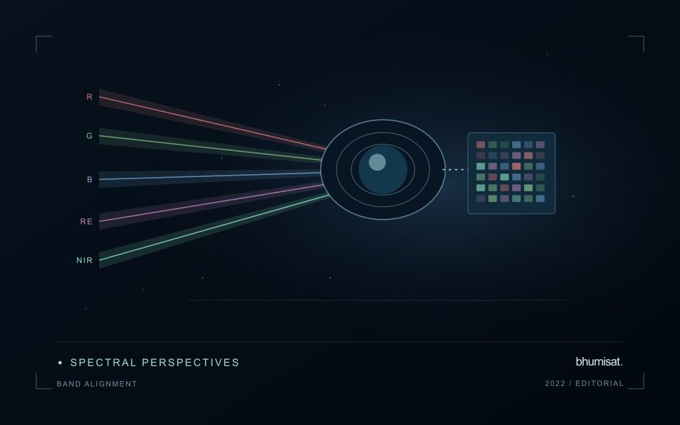
A multispectral analysis combines information from several channels, so their geographic relationship matters. If the channels are displaced, a calculation near a field boundary may combine vegetation in one band with a path, ditch or neighbouring surface in another. The resulting pattern can look like a meaningful spectral difference even though it is partly an alignment artefact. A workflow should therefore consider band alignment before producing indices, classifications or crop parameter estimates, particularly when the target landscape contains small fields and sharp transitions.
Alignment is not the same as assigning every band the same pixel dimensions. Bands may have different native sampling and observation characteristics. Resampling them onto one grid creates a shared representation, but it does not make all channels contain the same original spatial detail. The selected interpolation method can change values around edges and influence derived statistics. Record the target grid, coordinate reference system, pixel alignment and resampling choices so that another analyst can reproduce the combination and evaluate its consequences.
Assess the effects of resampling
Check alignment using features that can be recognised reliably in the relevant channels and are stable at the time of acquisition. Inspect several parts of the area rather than relying on one visually convenient location. A displacement may vary across the image or become more obvious in particular terrain. Quantitative checks should use suitable independent references and report the scale of the remaining error. A correction that appears convincing on a broad overview still needs examination at the spatial scale used by the application.
When evaluating an agricultural model, test whether alignment sensitivity changes its result. For example, compare field statistics with and without a documented interior boundary exclusion, or examine the effects of a small plausible displacement. Such checks help reveal whether a conclusion depends mainly on edge pixels. Avoid using repeated interpolation steps where one controlled transformation would suffice. A clear geometric processing chain makes spectral combinations more defensible and helps ensure that a reported crop difference reflects observations of comparable ground rather than a hidden mismatch between image channels.
The setting: Payload integration studies
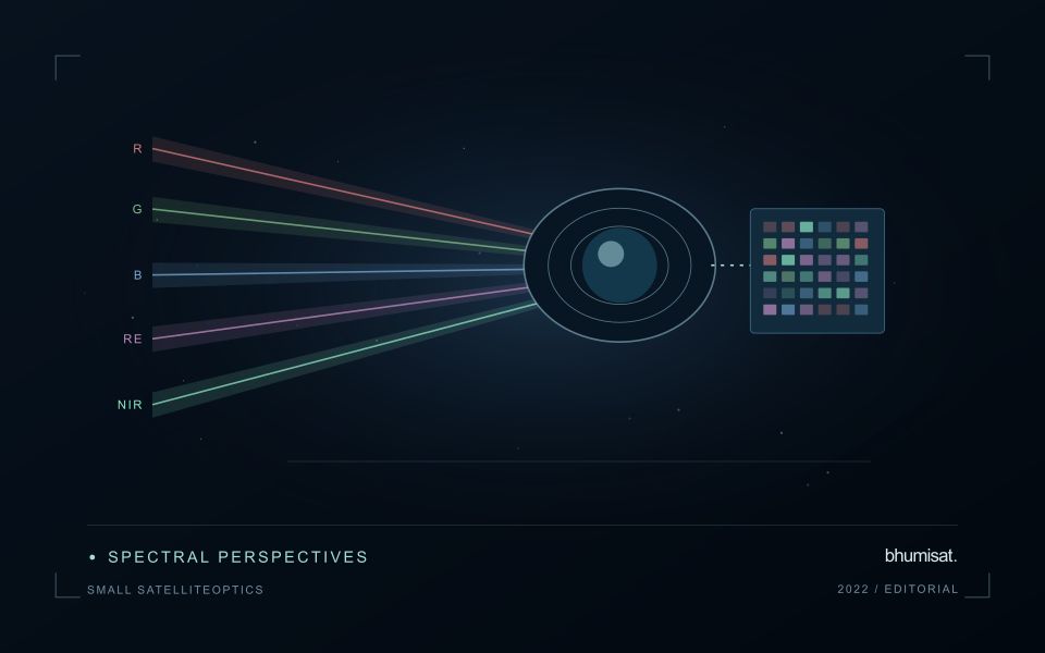
A payload integration study examines how an observation instrument behaves as part of a wider spacecraft concept. The camera, optics, electronics, structure and processing path cannot be assessed solely as independent catalogue items. Begin by identifying the measurements the complete system must support and the conditions under which they should be demonstrated. A component description can inform the design, but it does not establish the performance of an integrated imaging chain.
Test planning should record the hardware configuration, operating settings, reference targets and environmental conditions relevant to each measurement. Changes between tests need to remain traceable so that an apparent improvement is not confused with a different test setup. Spectral alignment, image geometry and radiometric consistency may interact with mechanical or thermal behaviour. The investigation should identify those relationships rather than relying only on whether an acquired test image looks visually sharp or colourful.
Acceptance criteria should connect instrument measurements with the needs of the intended application. Retain uncertainties, unsuccessful tests and design changes as part of the evidence used to evaluate progress. A laboratory demonstration under one condition should not be described as flight-qualified capability without the necessary additional work. A useful result at this stage is an auditable account of integrated behaviour, the remaining measurement questions and the next tests needed to assess the proposed payload architecture.
Design an evaluation that reflects deployment
A model evaluation should resemble the conditions in which the model will be used. Start by identifying which relationships the development data share: nearby locations, repeated observations of the same unit, common collection teams, or measurements from a single period. These relationships can make records less independent than they appear. An evaluation that ignores them may test the ability to recognise familiar conditions rather than the ability to operate in a new setting.
Choose a split strategy that matches the intended transfer. Holding out locations, seasons, operational units, or acquisition conditions can answer different questions. Document which question each split is designed to address, and keep the held-out evidence separate while selecting features and tuning the method. Repeatedly inspecting the same evaluation set to improve a model gradually makes that set part of development, even if it retains its original label.
Report results at a scale that is meaningful to the user. A strong average can hide poor performance for important subgroups or unusual conditions. Examine error patterns and retain examples of both successful and unsuccessful predictions. Where the evidence covers only a limited range of conditions, describe that range explicitly. The evaluation then becomes a practical guide to suitable use, further testing, and the collection of additional reference observations.
Check spatial alignment before comparison
A comparison between images, channels, maps, or field measurements assumes that the observations refer to the same locations at a suitable level of precision. Small alignment errors can become especially important near boundaries or narrow features. Before interpreting differences, inspect whether identifiable, stable features agree between the sources. A common coordinate reference is necessary for many workflows, but it does not by itself demonstrate accurate alignment.
Use control features that are appropriate for the observation scale and remain stable across the comparison period. Evaluate alignment in more than one part of the area, because a single location cannot reveal spatially varying distortion. Record the method used to estimate any correction and retain independent features for checking the corrected result. Where surfaces have genuinely changed, avoid using those changes as evidence of an alignment error.
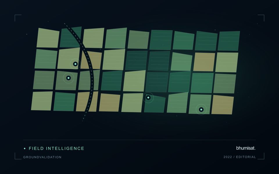
Propagate the implications of remaining misalignment into the analysis. A workflow may exclude boundary pixels, summarise at a broader scale, or qualify interpretations for small features. The choice should follow the application rather than a preference for visually smooth output. Preserve both the original and corrected geographic references, and document resampling decisions so that future users can understand how measurements were moved onto a common spatial framework.
Bring the evidence back to the decision
A strong interpretation states what was observed, which explanations remain plausible, and what additional evidence would help distinguish them. Avoid presenting a convenient label as a confirmed cause when the measurements support only a broader pattern. Connect the proposed next step to the significance of the decision and the confidence available. This creates an interpretation that a field team, analyst, or project partner can examine, challenge, and improve as further observations become available.
Sources & further reading
Explore the bhumisat spacecraft concept and our vision towards 2030, or return to the journal.