A convincing image can still contain measurements that are unsuitable for a particular task. Quality control asks whether the inputs, transformations, and outputs meet the requirements of the intended application. This perspective follows evidence through the workflow, from acquisition metadata and reference observations to the final interpretation. It encourages teams to define acceptance conditions before seeing the result, rather than adjusting them to favour a preferred conclusion. The purpose is a repeatable way to distinguish usable observations, observations requiring qualification, and observations that should be excluded from a decision.
This working guide considers spectral band alignment and common grids in onion production beds. The immediate decision is to review beds with uneven establishment. Useful reference evidence includes planting dates, bed cover and crop-stage observations. The case is an illustrative planning context, with assumptions to check against the actual sensor, landscape and project requirements.
A multiband value should refer to the same ground
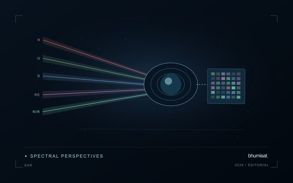
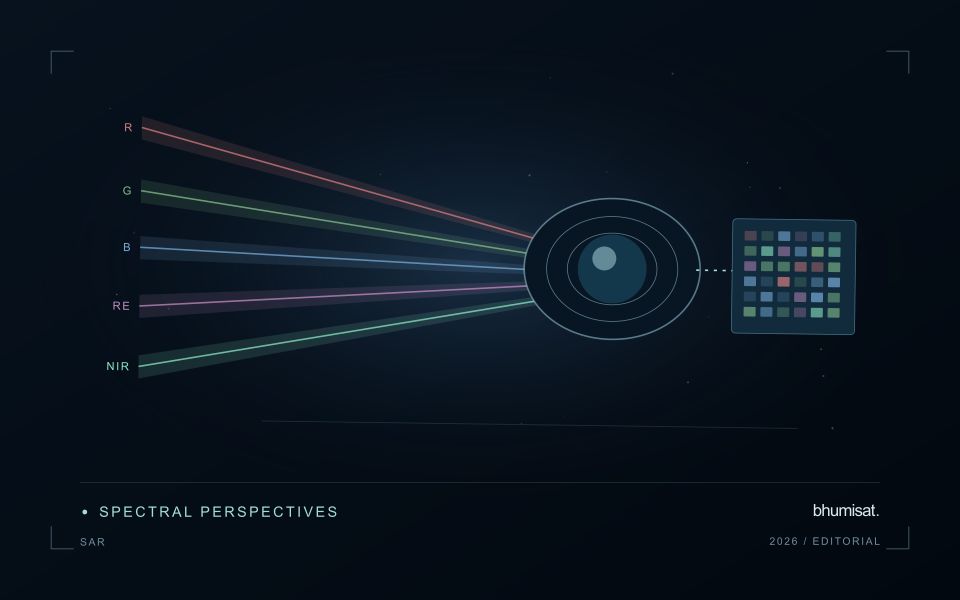
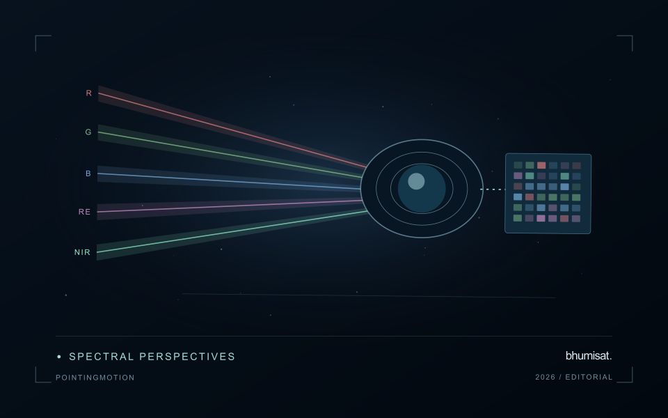
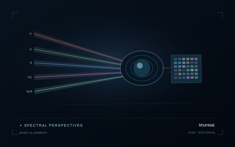
A multispectral analysis combines information from several channels, so their geographic relationship matters. If the channels are displaced, a calculation near a field boundary may combine vegetation in one band with a path, ditch or neighbouring surface in another. The resulting pattern can look like a meaningful spectral difference even though it is partly an alignment artefact. A workflow should therefore consider band alignment before producing indices, classifications or crop parameter estimates, particularly when the target landscape contains small fields and sharp transitions.
Alignment is not the same as assigning every band the same pixel dimensions. Bands may have different native sampling and observation characteristics. Resampling them onto one grid creates a shared representation, but it does not make all channels contain the same original spatial detail. The selected interpolation method can change values around edges and influence derived statistics. Record the target grid, coordinate reference system, pixel alignment and resampling choices so that another analyst can reproduce the combination and evaluate its consequences.
Assess the effects of resampling
Check alignment using features that can be recognised reliably in the relevant channels and are stable at the time of acquisition. Inspect several parts of the area rather than relying on one visually convenient location. A displacement may vary across the image or become more obvious in particular terrain. Quantitative checks should use suitable independent references and report the scale of the remaining error. A correction that appears convincing on a broad overview still needs examination at the spatial scale used by the application.
When evaluating an agricultural model, test whether alignment sensitivity changes its result. For example, compare field statistics with and without a documented interior boundary exclusion, or examine the effects of a small plausible displacement. Such checks help reveal whether a conclusion depends mainly on edge pixels. Avoid using repeated interpolation steps where one controlled transformation would suffice. A clear geometric processing chain makes spectral combinations more defensible and helps ensure that a reported crop difference reflects observations of comparable ground rather than a hidden mismatch between image channels.
The setting: Onion production beds
Onion fields can retain a strong soil contribution in optical imagery because of their canopy form and the arrangement of production beds. The proportion of exposed soil, the stage of the crop and the condition of neighbouring surfaces all matter to interpretation. A useful monitoring design begins by identifying whether it needs a field-level development indicator or more detailed bed-level information. The image data must genuinely support the scale at which conclusions are presented.
Maintain planting and management records alongside the image sequence, and distinguish normal stage differences from unusual spatial patterns. Small fields may contain only a limited number of observations that are not mixed with boundaries, tracks or other crops. Quality screening should account for this limitation rather than treating every nominal pixel as an independent view of onions. Comparable acquisition and processing conditions strengthen the interpretation of changes between reporting periods.
Field visits should record crop stage, stand continuity and the condition of the soil and bed surfaces contributing to the image. Sample across the mapped range, including areas that look typical, and preserve the location and date of each observation. A general reflectance pattern cannot directly establish bulb production or a named cause of stress. Those claims need appropriate measurements, while a transparent inspection-priority workflow can be evaluated through the outcomes of practical scouting visits.
Locate the uncertainty that matters to the decision
An uncertainty budget is a practical description of where a result could become unreliable. Begin with the observation chain: acquisition, calibration, geographic matching, reference measurements, feature calculation, modelling, and delivery. Identify the assumptions at each stage and ask which could materially change the interpretation. The purpose is not to assign a precise number to every limitation. It is to locate the sources that deserve attention for the intended decision.
Separate limitations that can be measured from those that currently require a qualitative description. Repeated measurements may help characterise variability, while comparisons with independent references can reveal systematic differences. Some uncertainties interact, so combining individual error estimates without examining their relationships can produce a misleading impression of precision. Keep the method of assessment visible and avoid treating an unexamined assumption as though it were a negligible contribution.
Use the budget to prioritise further work. The largest visible source of variation is not always the one whose reduction would most improve the decision. Consider which additional observation, test, or contextual record would change confidence in an actionable way. Revisit the budget when the application, observation source, or deployment conditions change. This turns uncertainty analysis into a guide for improving the workflow rather than a qualification added only after the result has been delivered.
Plan the evidence needed for calibration
Calibration connects an instrument's recorded response with a measurement that can be interpreted consistently. Begin by identifying which aspects of the response matter to the application: variation across channels, changes with operating conditions, geometric alignment, or differences between repeated observations. A calibration plan should state the quantities being assessed and the evidence needed to determine whether the response is sufficiently characterised for the intended use.
Design tests around controlled and documented conditions. Record the reference source, instrument configuration, exposure settings, temperature conditions, and processing applied to the measurements. Repeat suitable observations to investigate variability and distinguish a consistent response from a single favourable result. The reference itself has limitations, so preserve its characterisation and avoid assuming that every difference originates in the instrument under evaluation.
Connect calibration activities with the expected operating environment and processing chain. A correction that works under one test condition may require further evidence before being applied elsewhere. Define how calibration parameters are versioned, checked, and associated with the observations they support. Include a plan for recognising drift or other changes that could affect interpretation. The outcome should be an instrument response supported by traceable evidence, together with acceptance criteria that remain relevant to the application.
Bring the evidence back to the decision
Quality control is most useful when its results travel with the information being delivered. Preserve the reasons for accepting or rejecting an observation, and expose limitations that could change the user's interpretation. Review recurring failures as clues about the design of the workflow. A clear quality record supports consistent comparisons between operators and processing versions, while helping the team decide whether a problem originates in acquisition, preparation, interpretation, or the underlying observation requirements.
Sources & further reading
Explore the bhumisat spacecraft concept and our vision towards 2030, or return to the journal.